Interface Circuit Board Lab (ver. 2.1)
View a printable version of this page.
The Interface circuit board is relatively easy to construct. It has expansion capabilities which is the reason there are some unpopulated locations on the board. The photo can be used a guide for placement of the components.
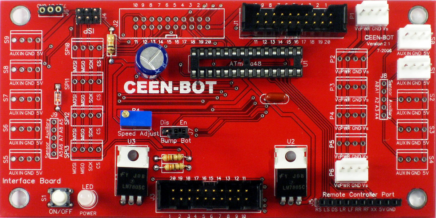
Open the bag of parts for the Interface board and sort them onto the Parts Map. Do this before you solder any components to minimize the chance of misreading a component's id and soldering it into the wrong location. Solder the components in the order shown on the parts map. The order is basically that the lowest profile items are soldered first. The dashed outlines on the parts map indicate components that must be oriented a specific way. Do not solder the integrated circuit on the board. It is placed into a socket.
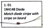
1. The first item to be soldered is the diode D1. Align the black stripe on the diode with the white stripe on the circuit board. See the Diode video.
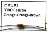
2. The second group of items is the resistors R1 and R2. The color bands tell the value. If in doubt, measure the value with the digital meter. These can be placed in either direction. See the Resistor video.
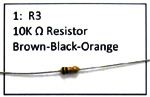
3. Place the resistor R3.
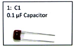
4. Capacitor C1. Orientation not critical.
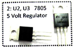
5. U2, U3. 7805 voltage regulators. See the 7805 video.
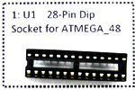
6. U1 Socket. Align u shaped notch on end of socket. See the IC_Socket video.
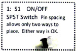
7. ON/OFF switch.
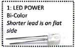
8. LED Power. Shorter lead is negative and has a flat side on the plastic body. The short lead is placed by the flat side on the silk screen.
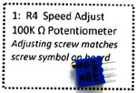
9. R4 Speed adjust potentiometer. Adjusting screw aligns with the screw head symbol on the circuit board. See the Potentiometer video.
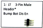
10. Solder the 3-pin male header for J7. See the Male_Header video for suggestions.
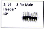
11. Solder the two 3-pin male header in J4.
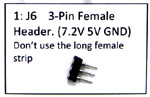
12. Solder the two 3-pin female machined sockets in J6. See the Mach_Female video.
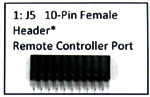
13. 10-pin female header J5. See video clip for suggestions.
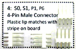
14. Connectors. S0, S1, P1, P6. Observe the photograph of the board to locate the places for these connectors. Not all the connector positions on the board will be populated.
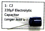
15. Capacitor C2. The longer lead is positive. Align with the + on the circuit board.
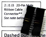
16. J1, J3. Male ribbon connectors. Check board photo for placement. The single notch in the housing faces the center of the board.
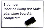
17. Press jumper on Bump Bot pins.
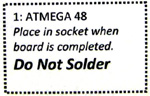
18. ATMEGA Microprocessor. DO NOT SOLDER. This may not be included in the parts. See ATMEGA video clip for suggestions.